How to Test the Restoring Force of a Bow Spring Casing Centralizer?
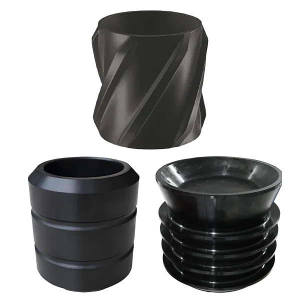
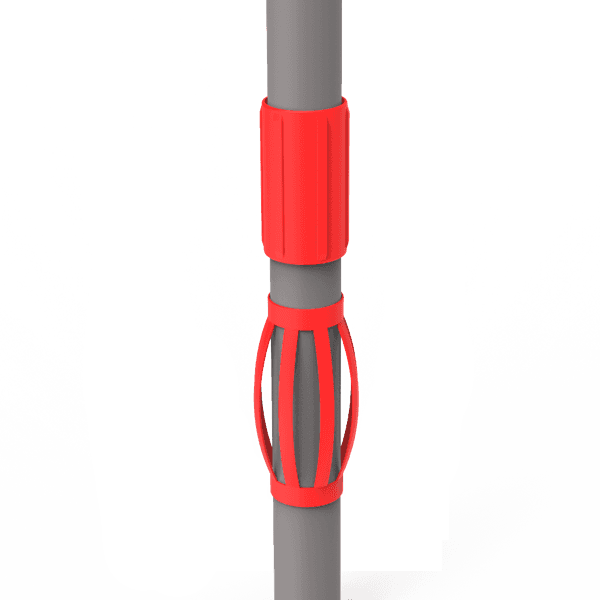
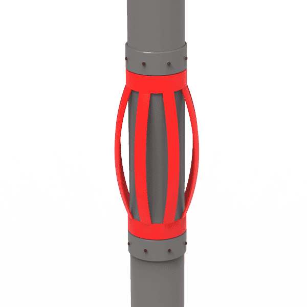
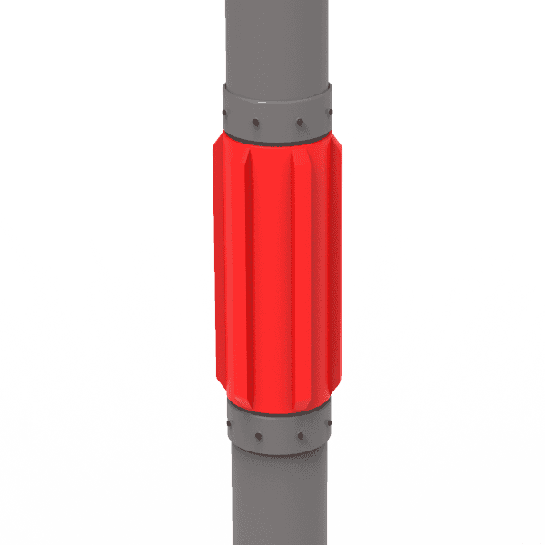
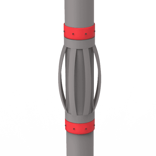
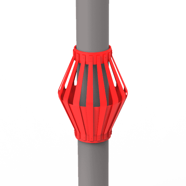
Bow spring centralizer is designed for primary cementing and applied in vertical, deviated and horizontal wells where low starting force and high restoring force are required.
Restoring force is a key parameter that measures the quality of bow spring centralizers. Here, we'd like to briefly introduce what the restoring force is, devices and samples required for restoring force testing, test procedures and results.
Restoring force refers to the force exerted by a centralizer against the casing to keep it away from the wellbore wall. The restoring force value varies as installation method changes.
Samples & Test Stand Preparation
- Samples
Get at least 6 prototype centralizers well prepared for design and process verification testing. All centralizers used shall conform to the performance requirements of Table 1.
- Test stand
The test stand allows the application of vertical loads and is capable of measuring these loads and vertical displacements.
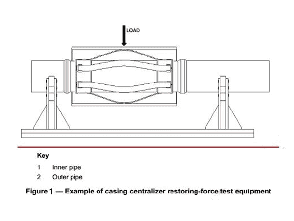
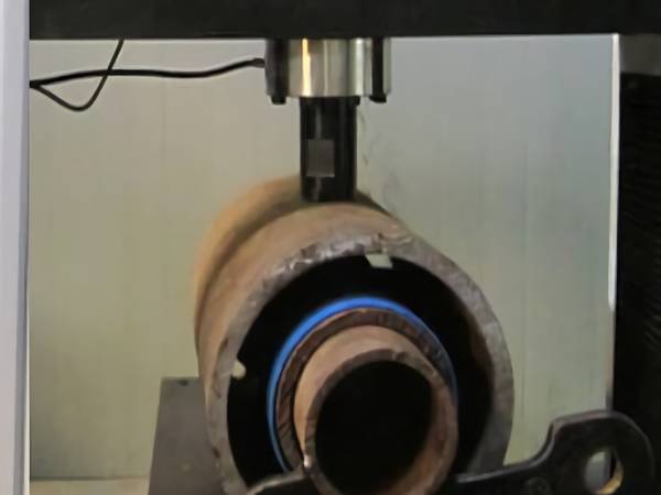
Example of casing centralizer restoring force test equipment
Casing centralizer restoring force test
- Instrumentation
Instrumentation of the test stand shall allow displacement readings of 1.6 mm (1/16") or smaller.
- Accuracy
- Accuracy of load measurements shall be within 5% of the measured value.
- Accuracy of displacement measurements shall be within 0.8 mm (1/32").
- All measuring devices shall be calibrated at least annually.
- Test Pipe
- Inner pipe
The inner pipe (Figure 1) shall be longer than the centralizer in the flexed condition and longer than the outer pipe. The outside diameter of the inner tube shall be within the tolerances shown in ISO 11960 for non-upset pipe. Burrs or similar defects shall be removed.
Surfaces on the ends of the inner pipe, outside the length to be covered by the centralizer and other test components, are exempt from the above requirements.
- Outer pipe
The outer pipe (Figure 1) shall be longer than the centralizer bow spring in the flexed condition. The inside diameter of the outer pipe shall be equal to the hole size for which the centralizer is designed. Tolerance shall fall within -0.8 mm to +3.2 mm (-1/31" to +1/8"). Burrs or similar defects shall be removed.
The end of the outer pipe (other than the upper end used for starting force tests), beyond the length covered by the centralizer when flexed during the restoring force test, is exempt from the above requirements.
Restoring Force Test Procedures
- When performing the test, the horizontal deviation of inner pipe and outer pipe shall be within 5°.
- Before collecting the force data for the test, flex all bow springs 12 times.
- Apply an external force to the outer pipe, so that it will be transferred to the inner pipe vertically through the point of contact of the centralizer within the outer pipe.
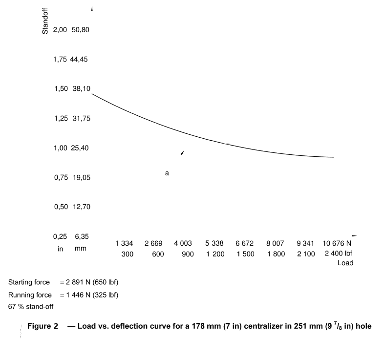
- Apply load and record load-deflection reading at a minimum of 1.6 mm (1/16") increments until three times (± 5%), the minimum restoring force has been obtained, see Figure 2. The travel distance to obtain 67% standoff shall be determined for each test position.
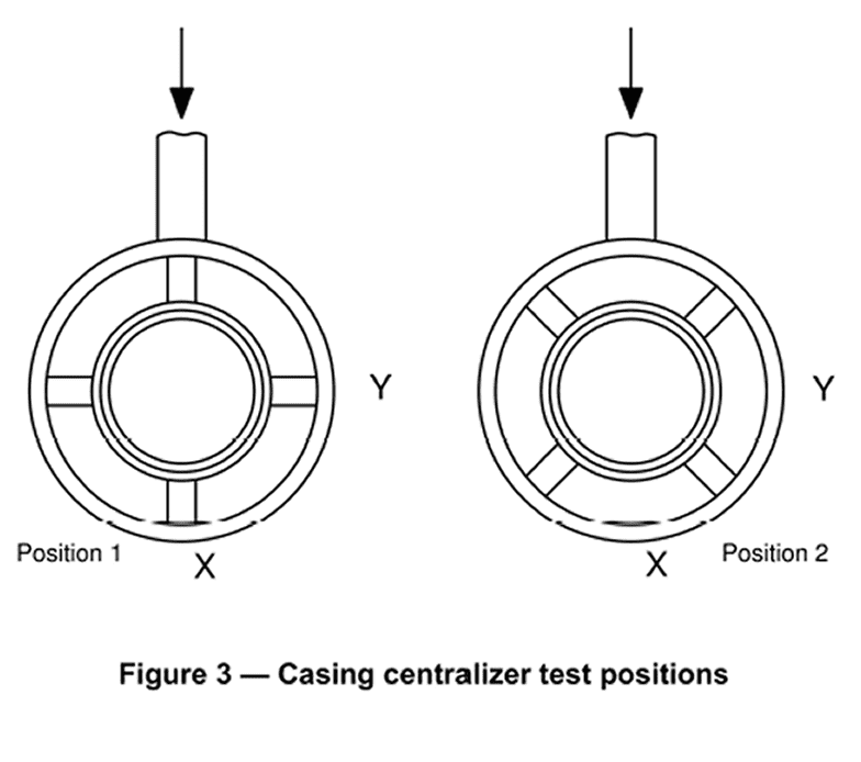
- Repeat the process, test the centralizer until each spring and each set of springs have been tested in position 1 and 2 as shown in Figure 3.
- Calculate the total load at each deflection by compensating for the mass of the travelling pipe and attachments.
- Prepare the final load-deflection curve using the arithmetic average of the force readings at corresponding deflections. Restoring force shall be determined from this curve at 67% standoff ratio.
Casing centralizer test positions
The minimum restoring force for a 67% standoff ratio shall not be less than the values shown in Table 1. See Determination of Restoring Force Requirements listed below for the derivation of the requirements.
Table 1 Casing Centralizer Specification – Restoring Force
| Casing Diameter |
Medium Linear Mass Casing |
Minimum Restoring Force at 67% Standoff Ratio |
| mm |
inch |
kg/m |
lb/ft |
N |
lbf |
| 89 |
3-1/2" |
14.7 |
9.91 |
1761 |
396 |
| 102 |
4" |
16.9 |
11.34 |
2019 |
454 |
| 114 |
4-1/2" |
17.3 |
11.6 |
2064 |
464 |
| 127 |
5" |
19.3 |
13.0 |
2313 |
520 |
| 140 |
5-1/2" |
23.1 |
15.5 |
2758 |
620 |
| 168 |
6-5/8" |
35.7 |
24.0 |
4270 |
960 |
| 178 |
7" |
38.7 |
26.0 |
4626 |
1040 |
| 194 |
7-5/8" |
39.3 |
26.4 |
4697 |
1056 |
| 219 |
8-5/8" |
53.6 |
36.0 |
6405 |
1440 |
| 244 |
9-5/8" |
59.5 |
40.0 |
7117 |
1600 |
| 273 |
10-3/4" |
75.9 |
51.0 |
4537 |
1020 |
| 298 |
11-3/4" |
80.4 |
54.0 |
4804 |
1080 |
| 340 |
1-3/8" |
90.8 |
61.0 |
5427 |
1220 |
| 406 |
16" |
96.7 |
65.0 |
5783 |
1300 |
| 473 |
18-5/8" |
130.2 |
87.5 |
7784 |
1750 |
| 508 |
20" |
139.9 |
94.0 |
8363 |
1880 |
NOTE:
- The specifications for restoring force for bow spring centralizers are based on the centralizer being installed as per manufacturer recommendations and tested with lugs on the casing. If the centralizer is tested over a casing collar, stop collar, or with an integral stop collar, the actual results obtained from that test can vary from the specifications. It should be noted on the test report how the centralizer was installed and the type of holding device used during the test. If a centralizer is tested in this manner, the test can no longer be considered a specification test and the results may or may not meet the specifications set forth in Table 1
- Casing diameter refers to the liner sizes.
- Medium linear mass casing refers to the plain-end weight.
|
Determination of Restoring Force Requirements
- Field observations indicate hole deviation from vertical on an average varies from zero to approximately 60°. Therefore, an average deviation of 30° is used to calculate restoring force requirements.
For casing diameters 273 mm (10-3/4") through 508 mm (20"), where casing strings are generally placed in relatively vertical hole sections, the minimum restoring force shall be not less than:
FR = W sin 30 = 0.5 W
Where
FR is the minimum restoring force, expressed in newtons;
W is the weight of 12.19 m (40 ft) of medium linear mass casing, expressed in newtons.
- For casing diameters 114 mm (4-1/2") through 244 mm (9-5/8"), where casing strings are generally placed in the deviated hole sections, the minimum restoring force shall be not less than:
FR = 2W sin 30 = W
The bow spring casing centralizer restoring force test shall be performed in strict accordance with requirements aforesaid.